Shaft-Friendly Clamping
The split closes around the shaft and avoids relying on a set screw bearing directly on one point of the shaft surface.
EP-SCS Series · 6 mm to 60 mm Bore
EP-SCS clamp collars provide a removable axial stop or locating reference on round shafts used in automation, linear motion, motor assemblies and general machinery. The range covers eighteen metric bore sizes, with model-specific outside diameter, width, screw, split and keyway data for practical fit checks.
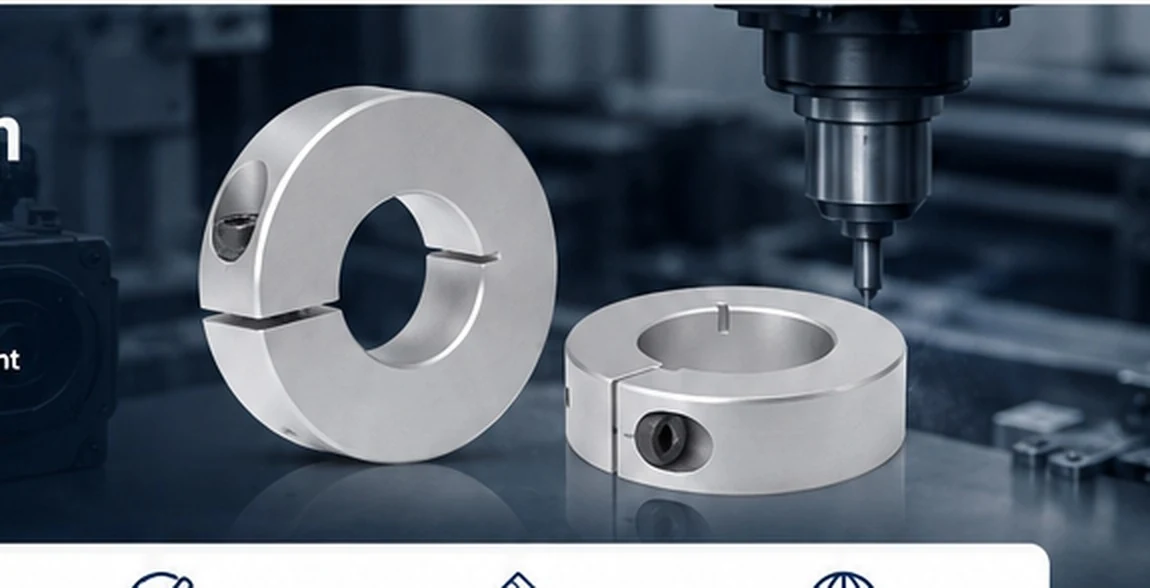 Precision machining & automation
Why Clamp Style
A single-split collar closes around the shaft through its clamp screw, distributing the clamping action around the bore instead of relying on one screw point against the shaft. That makes the format useful for adjustable stops, guide-shaft references and maintenance positions where the collar may need to be moved and reset.
The split closes around the shaft and avoids relying on a set screw bearing directly on one point of the shaft surface.
One collar can establish a stop; two collars can create an adjustable axial location window around another component.
Keyway K dimensions are listed for most models from EP-SCS10 upward, while the standard collar remains plain-bore.
Product Range
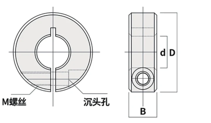
Start with the shaft diameter and open the model page that matches the measured bore. Each product page places the exact d/D/B/M/W/K values beside the dimensional drawing, then explains the envelope, screw access, keyway and RFQ checks that matter before ordering.
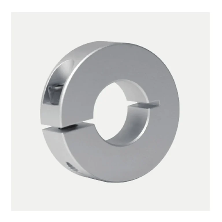
EP-SCS14: 14 mm bore, 35 mm OD, 12 mm width, M5 clamp screw, split W 1.5 mm, keyway K 5 mm option.
EP-SCS50: 50 mm bore, 85 mm OD, 22 mm width, M10 clamp screw, split W 3 mm, keyway K 14 mm option.
EP-SCS15: 15 mm bore, 35 mm OD, 12 mm width, M5 clamp screw, split W 1.5 mm, keyway K 5 mm option.
EP-SCS60: 60 mm bore, 95 mm OD, 22 mm width, M10 clamp screw, split W 3 mm, keyway K 18 mm option.
EP-SCS16: 16 mm bore, 35 mm OD, 12 mm width, M5 clamp screw, split W 1.5 mm, keyway K 5 mm option.
EP-SCS18: 18 mm bore, 40 mm OD, 12 mm width, M5 clamp screw, split W 1.5 mm, keyway K 6 mm option.
Applications
Axial positioning is a simple function, but the surrounding machine changes the selection details. A compact linear axis may be controlled by carriage clearance, while a motor or industrial-machine assembly may be controlled by neighboring couplings, guards, bearings or service access.
 CNC & AutomationGuide-shaft stops, axial references and compact machine positioning.
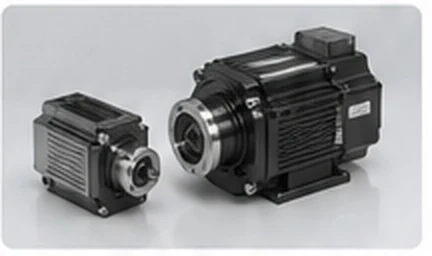 Motors & DrivesLocation beside couplings, pulleys and other shaft-mounted components.
 Robotics & 3D PrintingLightweight stops and locators on lead screws and guide shafts.
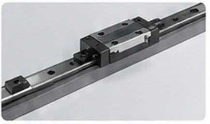 Industrial MachineryMechanical stops and component location in packaging, conveying and custom machinery.
Series Selection
Match bore d to the measured shaft first. After that, verify outside diameter D, body width B and access to the clamp screw, because a nominally correct bore can still interfere with a frame, bearing block, pulley, carriage or guard.
If a keyway is required, use the listed K value only as the collar-side reference and include the mating key and shaft geometry in the enquiry. For replacement work, add a photo or sketch when the available space is not obvious from the shaft diameter alone.
Technical Reference
The chart lets buyers compare the entire metric range without jumping between product pages. Use it to shortlist a model, then open the specific product page for installation-space checks and enquiry guidance.
| Model | Bore d (mm) | OD D (mm) | Width B (mm) | Screw M | Split W (mm) | Keyway K (mm) |
|---|---|---|---|---|---|---|
| EP-SCS06 | 6 | 20 | 10 | M4 | 1 | — |
| EP-SCS08 | 8 | 30 | 10 | M4 | 1.5 | — |
| EP-SCS10 | 10 | 30 | 10 | M4 | 1.5 | 3 |
| EP-SCS12 | 12 | 30 | 10 | M4 | 1.5 | 4 |
| EP-SCS13 | 13 | 30 | 10 | M4 | 1.5 | 4 |
| EP-SCS14 | 14 | 35 | 12 | M5 | 1.5 | 5 |
| EP-SCS15 | 15 | 35 | 12 | M5 | 1.5 | 5 |
| EP-SCS16 | 16 | 35 | 12 | M5 | 1.5 | 5 |
| EP-SCS18 | 18 | 40 | 12 | M5 | 1.5 | 6 |
| EP-SCS20 | 20 | 40 | 12 | M5 | 1.5 | 6 |
| EP-SCS22 | 22 | 45 | 12 | M5 | 1.5 | 6 |
| EP-SCS25 | 25 | 45 | 12 | M5 | 1.5 | 8 |
| EP-SCS30 | 30 | 55 | 15 | M6 | 1.5 | 8 |
| EP-SCS35 | 35 | 60 | 15 | M6 | 2 | 10 |
| EP-SCS40 | 40 | 70 | 18 | M8 | 2 | 12 |
| EP-SCS45 | 45 | 80 | 22 | M10 | 2 | 14 |
| EP-SCS50 | 50 | 85 | 22 | M10 | 3 | 14 |
| EP-SCS60 | 60 | 95 | 22 | M10 | 3 | 18 |
Knowledge Base
Use the engineering articles when the buying question is broader than one bore size. Topics cover collar-style comparison, size selection, installation, keyway decisions, CNC applications, shaft-surface care and custom-order preparation.
Prepare a custom RFQ with the dimensions and application details needed for review.
Read Article →Navigate the EP-SCS bore range by shaft size, envelope and machine context.
Read Article →Selection and installation practices that reduce avoidable shaft marking and fit problems.
Read Article →RFQ Support
Send shaft diameter, preferred EP-SCS model, quantity, keyway requirement and a drawing or photo when the fit is tight. Add any application-critical requirement such as impact, unusual environment or documentation so it can be addressed in the quotation.