Engineering Note
6mm to 60mm Shaft Clamps: Choosing the Right Size
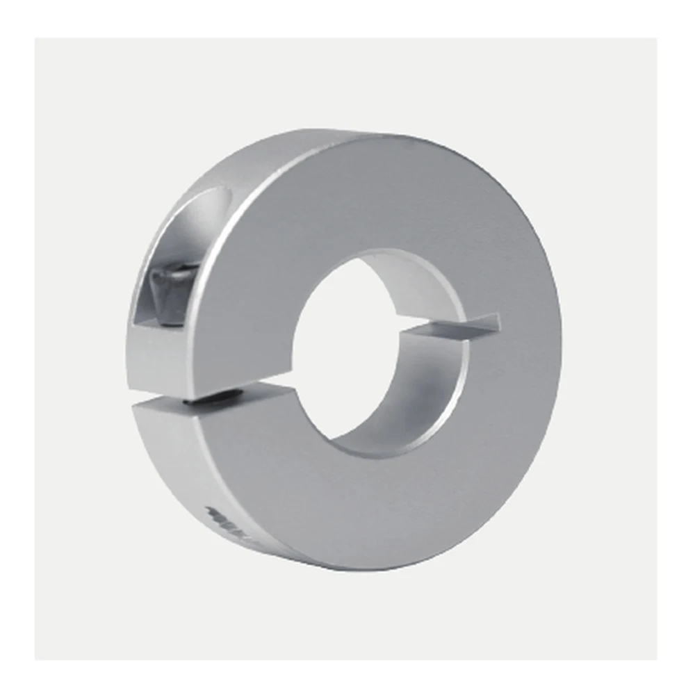
The EP-SCS series spans eighteen metric bores from 6 mm to 60 mm, but the model number should not be treated as the entire selection decision. As the bore increases, the outside diameter, width and clamp screw also change, and those changes affect installation space and service access.
A practical way to navigate the range is to group models by machine scale, then return to the exact dimensions for the measured shaft.
6–12 mm: Compact Guide and Fixture Hardware
EP-SCS06 through EP-SCS12 use 10 mm body widths and M4 screws. These sizes are natural candidates for small guide rods, instrument fixtures, compact automation and light bench mechanisms where a removable stop or position reference is required.
At this scale, outside diameter and measurement accuracy matter greatly. Check sensor brackets, small carriages and end plates because the collar envelope can still control the available space around a slender shaft.
13–25 mm: General Automation and Linear Motion
This band includes several intermediate metric sizes such as 13, 14, 15, 16, 18, 20, 22 and 25 mm. It is useful for general factory automation, linear-motion hardware, fixture positioning and maintenance replacements where the machine does not use only round-number shaft sizes.
Compare the actual shaft, radial envelope and clamp-screw access. The collar can be easy to position initially but difficult to service later if the screw faces a frame or cover.
30–60 mm: Larger Machinery Interfaces
From EP-SCS30 upward, outside diameter and body width increase and the series moves through M6, M8 and M10 screws. These larger models should be integrated as deliberate machine components with enough radial space, axial space and service access.
Describe the application duty clearly, especially if the collar may receive repeated impact or meaningful axial demand. Bore size alone is not a performance rating.
Complete Range
| Model | Bore d (mm) | OD D (mm) | Width B (mm) | Screw M | Split W (mm) | Keyway K (mm) |
|---|---|---|---|---|---|---|
| EP-SCS06 | 6 | 20 | 10 | M4 | 1 | — |
| EP-SCS08 | 8 | 30 | 10 | M4 | 1.5 | — |
| EP-SCS10 | 10 | 30 | 10 | M4 | 1.5 | 3 |
| EP-SCS12 | 12 | 30 | 10 | M4 | 1.5 | 4 |
| EP-SCS13 | 13 | 30 | 10 | M4 | 1.5 | 4 |
| EP-SCS14 | 14 | 35 | 12 | M5 | 1.5 | 5 |
| EP-SCS15 | 15 | 35 | 12 | M5 | 1.5 | 5 |
| EP-SCS16 | 16 | 35 | 12 | M5 | 1.5 | 5 |
| EP-SCS18 | 18 | 40 | 12 | M5 | 1.5 | 6 |
| EP-SCS20 | 20 | 40 | 12 | M5 | 1.5 | 6 |
| EP-SCS22 | 22 | 45 | 12 | M5 | 1.5 | 6 |
| EP-SCS25 | 25 | 45 | 12 | M5 | 1.5 | 8 |
| EP-SCS30 | 30 | 55 | 15 | M6 | 1.5 | 8 |
| EP-SCS35 | 35 | 60 | 15 | M6 | 2 | 10 |
| EP-SCS40 | 40 | 70 | 18 | M8 | 2 | 12 |
| EP-SCS45 | 45 | 80 | 22 | M10 | 2 | 14 |
| EP-SCS50 | 50 | 85 | 22 | M10 | 3 | 14 |
| EP-SCS60 | 60 | 95 | 22 | M10 | 3 | 18 |
Keyway Progression
The standard collar remains plain-bore across the range. K dimensions are listed from EP-SCS10 upward, while the two smallest models do not show a standard K value.
For any keyed request, include the mating key and shaft geometry. Larger bore does not remove the need to define the complete keyed interface.
One Selection Rule Across All Sizes
Measure the shaft, choose the matching bore, check outside diameter and width, confirm screw access and then describe the collar’s role. Add a drawing or photo for replacement work and list any environment, impact or documentation requirement that affects the order.
Need Help Narrowing the Range?
Use the Selection Guide for a step-by-step workflow or send your shaft and machine dimensions through the RFQ form. A few measured values usually narrow the eighteen-model range quickly.