Shaft-Friendly Clamping
The split design closes around the shaft and avoids relying on a set screw bearing directly on one point of the shaft.
EP-SCS Series · 6 mm to 60 mm Bore
Clamp-style aluminum shaft collars for guide-shaft stops, rotating-part location and adjustable machine positioning. Choose from eighteen metric bore sizes with optional keyway dimensions listed across most of the range.
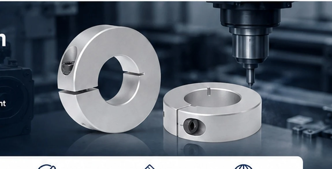 Application visualization
Why Clamp Style
The split design closes around the shaft and avoids relying on a set screw bearing directly on one point of the shaft.
Use one collar as a stop or two collars around a component where the axial position needs adjustment.
Keyway dimensions are listed for EP-SCS10 through EP-SCS60; standard collars are supplied without a keyway.
Live Catalogue
The homepage and Products page use the same WooCommerce records so model names, dimensions and links stay consistent.
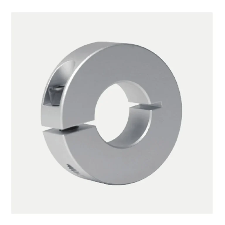
EP-SCS18: 18 mm bore, 40 mm OD, 12 mm width, M5 clamp screw, split W 1.5 mm, keyway K 6 mm option.
EP-SCS20: 20 mm bore, 40 mm OD, 12 mm width, M5 clamp screw, split W 1.5 mm, keyway K 6 mm option.
EP-SCS22: 22 mm bore, 45 mm OD, 12 mm width, M5 clamp screw, split W 1.5 mm, keyway K 6 mm option.
EP-SCS06: 6 mm bore, 20 mm OD, 10 mm width, M4 clamp screw, split W 1 mm. No standard keyway K dimension…
EP-SCS25: 25 mm bore, 45 mm OD, 12 mm width, M5 clamp screw, split W 1.5 mm, keyway K 8 mm option.
EP-SCS08: 8 mm bore, 30 mm OD, 10 mm width, M4 clamp screw, split W 1.5 mm. No standard keyway K dimension…
Applications
 CNC & AutomationGuide-shaft stops, axial references and compact machine positioning.
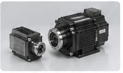 Motors & DrivesLocation beside couplings, pulleys and other shaft-mounted components.
 Robotics & 3D PrintingLightweight stops and locators on lead screws and guide shafts.
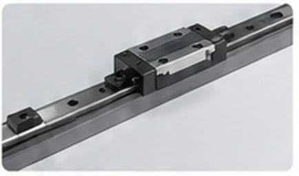 Industrial MachineryMechanical stops and component location in general machinery.
Series Selection
Match the nominal bore to the shaft diameter, then confirm outside diameter, body width and clamp-screw access. If a keyway is required, use the listed K dimension as a starting point and include mating key details in the RFQ.
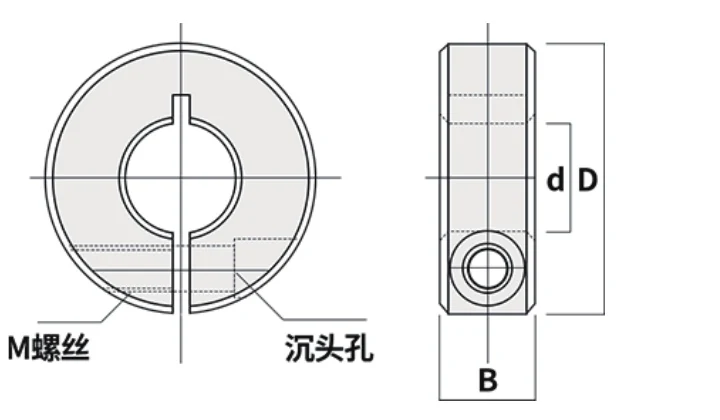
Technical Reference
| Model | Bore d (mm) | OD D (mm) | Width B (mm) | Screw M | Split W (mm) | Keyway K (mm) |
|---|---|---|---|---|---|---|
| EP-SCS06 | 6 | 20 | 10 | M4 | 1 | — |
| EP-SCS08 | 8 | 30 | 10 | M4 | 1.5 | — |
| EP-SCS10 | 10 | 30 | 10 | M4 | 1.5 | 3 |
| EP-SCS12 | 12 | 30 | 10 | M4 | 1.5 | 4 |
| EP-SCS13 | 13 | 30 | 10 | M4 | 1.5 | 4 |
| EP-SCS14 | 14 | 35 | 12 | M5 | 1.5 | 5 |
| EP-SCS15 | 15 | 35 | 12 | M5 | 1.5 | 5 |
| EP-SCS16 | 16 | 35 | 12 | M5 | 1.5 | 5 |
| EP-SCS18 | 18 | 40 | 12 | M5 | 1.5 | 6 |
| EP-SCS20 | 20 | 40 | 12 | M5 | 1.5 | 6 |
| EP-SCS22 | 22 | 45 | 12 | M5 | 1.5 | 6 |
| EP-SCS25 | 25 | 45 | 12 | M5 | 1.5 | 8 |
| EP-SCS30 | 30 | 55 | 15 | M6 | 1.5 | 8 |
| EP-SCS35 | 35 | 60 | 15 | M6 | 2 | 10 |
| EP-SCS40 | 40 | 70 | 18 | M8 | 2 | 12 |
| EP-SCS45 | 45 | 80 | 22 | M10 | 2 | 14 |
| EP-SCS50 | 50 | 85 | 22 | M10 | 3 | 14 |
| EP-SCS60 | 60 | 95 | 22 | M10 | 3 | 18 |
Knowledge Base
Prepare a custom RFQ with the dimensions and application details needed for review.
Read Article →Navigate the EP-SCS bore range by shaft size, envelope and machine context.
Read Article →Selection and installation practices that reduce avoidable shaft marking and fit problems.
Read Article →RFQ Support
Send shaft diameter, preferred EP-SCS model, quantity, keyway requirement and a drawing or photo when fit is tight.