Engineering Note
Shaft Clamp Size Chart: How to Select Bore and Outer Diameter
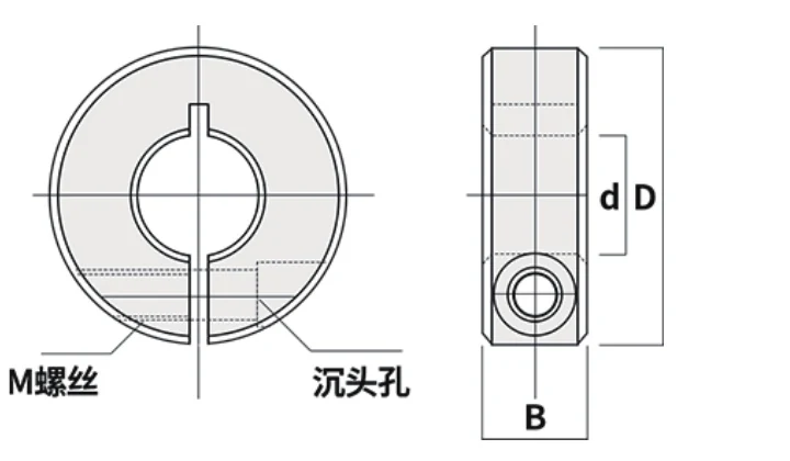
A shaft-clamp size chart is most useful when it is read as an interface map rather than a list of bores. Bore d identifies the starting shaft size, but outside diameter D, width B, clamp screw M, split W and keyway K determine whether the collar can actually be installed in the machine.
The EP-SCS range covers 6–60 mm nominal bores. The selection sequence below helps buyers narrow the table without overlooking the surrounding envelope.
Read Bore d First
Measure the shaft at the intended collar position and find the matching nominal bore. On replacement equipment, do not rely only on the machine name or an old collar marking because wear, coatings or previous modifications can change the practical fit question.
Bore selection should not be used to compensate for an uncertain measurement. If the shaft size is unclear, resolve that uncertainty before moving to the rest of the chart.
Then Check Outside Diameter D
D controls the radial envelope around the shaft. Compare it with frames, bearing blocks, pulleys, couplings, guards, sensors and moving carriages, especially on compact machinery where a few millimetres of additional radius can create interference.
For a retrofit, record the largest outside diameter the machine can accept rather than assuming that a collar with the right bore will fit.
Check Width B and Screw Access
B controls the axial space occupied by the collar. Width becomes important near shaft shoulders, bearings, spacers and other components that already use the available axial length.
The screw size identifies the service interface, but the screw must also be reachable in the assembled machine. Orient the collar so the tool path remains accessible after guards and neighboring components are installed.
EP-SCS Complete Size Chart
| Model | Bore d (mm) | OD D (mm) | Width B (mm) | Screw M | Split W (mm) | Keyway K (mm) |
|---|---|---|---|---|---|---|
| EP-SCS06 | 6 | 20 | 10 | M4 | 1 | — |
| EP-SCS08 | 8 | 30 | 10 | M4 | 1.5 | — |
| EP-SCS10 | 10 | 30 | 10 | M4 | 1.5 | 3 |
| EP-SCS12 | 12 | 30 | 10 | M4 | 1.5 | 4 |
| EP-SCS13 | 13 | 30 | 10 | M4 | 1.5 | 4 |
| EP-SCS14 | 14 | 35 | 12 | M5 | 1.5 | 5 |
| EP-SCS15 | 15 | 35 | 12 | M5 | 1.5 | 5 |
| EP-SCS16 | 16 | 35 | 12 | M5 | 1.5 | 5 |
| EP-SCS18 | 18 | 40 | 12 | M5 | 1.5 | 6 |
| EP-SCS20 | 20 | 40 | 12 | M5 | 1.5 | 6 |
| EP-SCS22 | 22 | 45 | 12 | M5 | 1.5 | 6 |
| EP-SCS25 | 25 | 45 | 12 | M5 | 1.5 | 8 |
| EP-SCS30 | 30 | 55 | 15 | M6 | 1.5 | 8 |
| EP-SCS35 | 35 | 60 | 15 | M6 | 2 | 10 |
| EP-SCS40 | 40 | 70 | 18 | M8 | 2 | 12 |
| EP-SCS45 | 45 | 80 | 22 | M10 | 2 | 14 |
| EP-SCS50 | 50 | 85 | 22 | M10 | 3 | 14 |
| EP-SCS60 | 60 | 95 | 22 | M10 | 3 | 18 |
Understand the Keyway K Column
The standard collar is plain-bore. K values are listed for most models from 10 mm upward, while the two smallest models do not show a standard K dimension.
If a keyed collar is required, send the mating key and shaft geometry. K is only one collar-side dimension and should not be treated as the complete keyed-interface definition.
Use Bore Bands to Shortlist the Range
The 6–12 mm models occupy the compact end of the range and are natural candidates for small guide rods and light automation. The 13–25 mm group covers many general machine and linear-motion sizes, while 30–60 mm models require increasing attention to the radial envelope, body width and service access around larger shaft arrangements.
These bands are navigation aids, not performance classes. The application duty still needs to be described separately from the bore size.
Selection Example
If a machine uses a measured 20 mm shaft, EP-SCS20 is the first model to evaluate. The buyer should then check the 40 mm outside diameter, 12 mm width and M5 screw access against the actual assembly, and confirm whether the listed 6 mm keyway option is relevant to the mating shaft.
If any one of those dimensions conflicts with the machine, the answer is not automatically to choose another bore. Recheck the interface and send a drawing when a non-standard option is required.
RFQ Checklist
Send the selected model or shaft diameter, quantity, keyway need, available OD/width and the collar’s intended role. Include a drawing or photo for replacement work, compact mechanisms or any assembly where the surrounding components are difficult to describe.