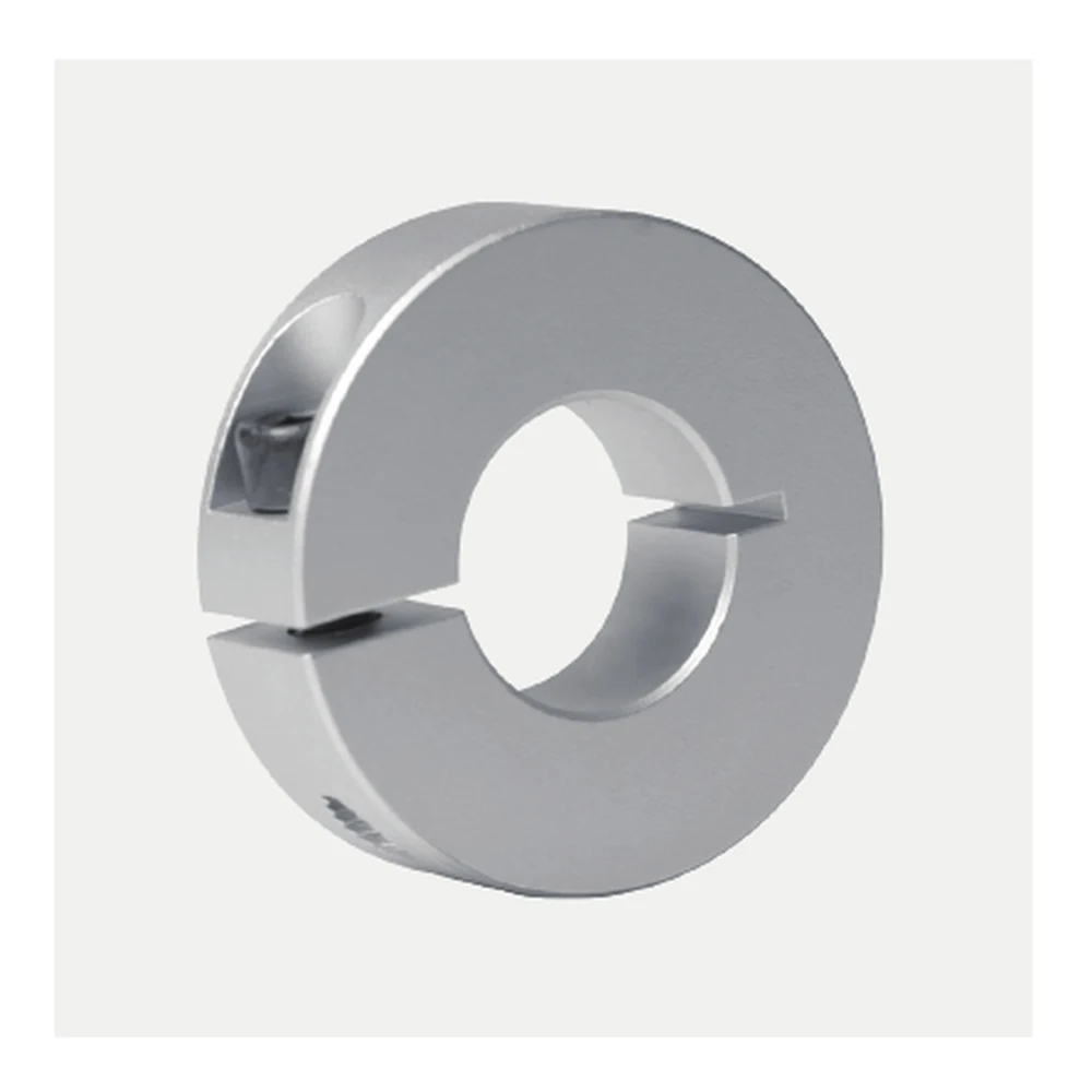
40 mm drive and machine-layout positioning
EP-SCS40 is a single-split aluminum shaft clamp with a 40 mm nominal bore, 70 mm outside diameter, 18 mm width and M8 clamp screw. It is intended for axial positioning and stop duties on round shafts where a clamp-style collar gives the installer a removable, repositionable mechanical reference.
Where EP-SCS40 Fits Best
At 40 mm bore, the series steps to a 70 mm outside diameter, 18 mm body width and M8 clamp screw. This model belongs in a larger machine envelope where bearing housings, pulleys, couplings and guards should be checked together with the collar.
EP-SCS40 belongs to the larger-bore portion of the EP-SCS range and should be reviewed as part of the complete machine interface rather than as a bore-only item. Its 70 mm outside diameter and 18 mm width make radial space, axial space and service access increasingly important in machinery and retrofit layouts.
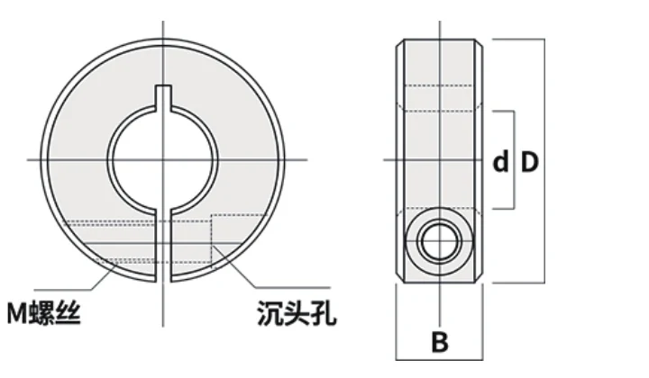
Model Dimensions
| Model | Bore d | OD D | Width B | Screw M | Split W | Keyway K |
|---|---|---|---|---|---|---|
| EP-SCS40 | 40 mm | 70 mm | 18 mm | M8 | 2 mm | 12 mm |
Selection starts with the measured shaft diameter, then moves to the surrounding envelope. Confirm the 70 mm outside diameter, 18 mm axial width and access to the M8 screw against the real assembly before treating EP-SCS40 as a replacement or new-build fit.
Interface Review
A 70 mm outside diameter can be the deciding fit dimension near a motor or drive component. Use the machine drawing to confirm radial clearance and screw-tool approach before treating the nominal 40 mm bore as sufficient evidence of fit.
The EP-SCS chart lists K = 12 mm for the keyed option on EP-SCS40, while the standard collar is supplied without a keyway. A keyed request should include the mating key and shaft details because the K value is only one dimension of the complete interface.
Typical Positioning Roles
EP-SCS40 can serve as a removable stop on a 40 mm guide shaft, an axial reference beside another shaft-mounted component, or one side of a paired locating arrangement. Its 18 mm body width and 70 mm outside diameter must fit the surrounding mechanism; bearings, couplings, keys and other functional components should continue to perform the duties assigned to them by the machine design.
If EP-SCS40 is intended to act as a hard stop rather than a setup reference, describe the contact event in the enquiry. Repeated impact on a 40 mm shaft creates a different selection question from occasional positioning, even though the listed collar dimensions are unchanged.
Installation and Service Considerations
If the collar is only an axial locator beside a rotating element, make sure the rotating element’s own retention and torque transfer remain independently defined. The collar should not inherit functions that are not stated in its technical data.
For the larger EP-SCS40 interface, reserve working space around the M8 screw as well as the full 70 mm radial envelope and 18 mm body width. If the 40 mm shaft stop will see repeated impact, meaningful axial demand or another demanding duty, state that condition in the RFQ so it can be reviewed for this configuration.
The EP-SCS40 body is tightened through its M8 clamp screw and the listed split W is 2 mm. Install it on a clean 40 mm shaft, seat the collar squarely, keep the screw accessible, and verify the axial position again after tightening before the mechanism returns to service.
Configuration Details to Confirm
The size chart defines the core geometry for EP-SCS40. If the application depends on a specific tightening torque, axial holding requirement, aluminum grade, surface treatment or compliance document, state that requirement in the RFQ so it can be confirmed for the ordered configuration rather than assumed from bore size alone.
When EP-SCS40 is being considered as a replacement, record the actual shaft diameter together with the old collar outside diameter, width and screw orientation. Also note nearby shoulders, bearing hardware and visible shaft condition so the 70 mm × 18 mm envelope can be checked against the installation rather than inferred from the machine name.
Nearest EP-SCS Bore Options
EP-SCS40 is centered on a 40 mm shaft interface. Nearby catalogue entries such as EP-SCS35 and EP-SCS45 are useful for comparing the range, but they should not be used to compensate for an uncertain shaft measurement. Verify the shaft first, then treat the 70 mm OD and 18 mm width as separate envelope checks.
RFQ Focus for EP-SCS40
Provide the 40 mm shaft measurement, available radial/axial space, quantity and whether the listed 12 mm K option is needed. Include duty details if the collar may see substantial axial force.
For EP-SCS40, identify whether the collar will be a fixed stop, adjustable setup reference, paired locator or keyed interface. Include that role with the 40 mm shaft dimension, quantity and any restricted 70 mm OD / 18 mm width envelope so the quotation addresses the real assembly.