Engineering Note
EP-SCS Series Shaft Clamp Technical Guide
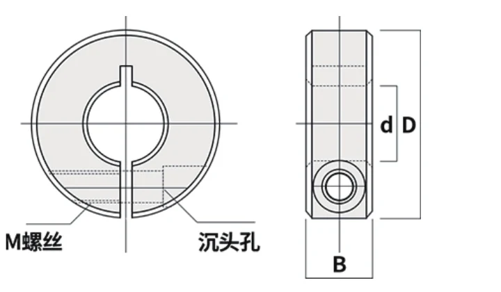
The EP-SCS family is a metric range of single-split aluminum shaft clamps covering nominal bores from 6 mm to 60 mm. The models are intended for axial positioning, guide-shaft stops and general mechanical locating roles where a removable clamp collar fits the machine layout.
This guide brings the family into one selection framework: what the dimensions mean, how the range changes with bore, where keyway data appears, and what additional application information should be included before ordering.
Core Geometry of the Series
Each model is identified by bore d, outside diameter D, width B, clamp screw M and split W. Keyway K is listed for most sizes from EP-SCS10 upward; the standard collar itself is plain-bore.
These parameters describe the collar envelope and fastening interface. They should be compared with the actual shaft and surrounding machine rather than interpreted as a complete performance rating.
EP-SCS Complete Technical Table
| Model | Bore d (mm) | OD D (mm) | Width B (mm) | Screw M | Split W (mm) | Keyway K (mm) |
|---|---|---|---|---|---|---|
| EP-SCS06 | 6 | 20 | 10 | M4 | 1 | — |
| EP-SCS08 | 8 | 30 | 10 | M4 | 1.5 | — |
| EP-SCS10 | 10 | 30 | 10 | M4 | 1.5 | 3 |
| EP-SCS12 | 12 | 30 | 10 | M4 | 1.5 | 4 |
| EP-SCS13 | 13 | 30 | 10 | M4 | 1.5 | 4 |
| EP-SCS14 | 14 | 35 | 12 | M5 | 1.5 | 5 |
| EP-SCS15 | 15 | 35 | 12 | M5 | 1.5 | 5 |
| EP-SCS16 | 16 | 35 | 12 | M5 | 1.5 | 5 |
| EP-SCS18 | 18 | 40 | 12 | M5 | 1.5 | 6 |
| EP-SCS20 | 20 | 40 | 12 | M5 | 1.5 | 6 |
| EP-SCS22 | 22 | 45 | 12 | M5 | 1.5 | 6 |
| EP-SCS25 | 25 | 45 | 12 | M5 | 1.5 | 8 |
| EP-SCS30 | 30 | 55 | 15 | M6 | 1.5 | 8 |
| EP-SCS35 | 35 | 60 | 15 | M6 | 2 | 10 |
| EP-SCS40 | 40 | 70 | 18 | M8 | 2 | 12 |
| EP-SCS45 | 45 | 80 | 22 | M10 | 2 | 14 |
| EP-SCS50 | 50 | 85 | 22 | M10 | 3 | 14 |
| EP-SCS60 | 60 | 95 | 22 | M10 | 3 | 18 |
How the Range Changes With Bore
Small-bore models use compact outside diameters, narrow widths and M4/M5 screws. As bore increases, the collar grows in outside diameter and body width and moves through M6, M8 and M10 clamp screws.
This progression means the main selection risk also changes. Compact models are often controlled by carriage or sensor clearance, while larger models increasingly require deliberate radial space, axial space and service access in the machine layout.
Typical Mechanical Roles
A single collar can establish an axial stop or reference on a round shaft. Two collars can be placed around another shaft-mounted part to define an adjustable location window when the machine design requires that arrangement.
The collar should not automatically replace bearings, couplings, shaft shoulders, keys or other components that have separate functional responsibilities. Describe the intended role clearly when the application is more demanding than a simple locator.
Keyway Options
EP-SCS06 and EP-SCS08 do not show a standard K dimension. From EP-SCS10 upward, K values are listed by model, but a keyed RFQ should still include the mating key and shaft geometry because one dimension cannot define the entire interface.
Selection Sequence
| Step | Decision |
|---|---|
| 1 | Measure the actual shaft at the collar position. |
| 2 | Select the matching nominal bore. |
| 3 | Check OD D and width B against the installation envelope. |
| 4 | Confirm screw access and keyway requirements. |
| 5 | Describe the collar role and any impact/environment/documentation requirements. |
| 6 | Send a photo or drawing for replacements and tight-fit assemblies. |
Application-Critical Details
If the order depends on a specific tightening torque, axial holding requirement, aluminum grade, surface treatment or compliance document, include that requirement in the RFQ. Those items should be tied to the ordered configuration and application rather than inferred from a generic bore size.
Where to Go Next
Use the Products page to open the exact EP-SCS model, the Selection Guide for a dimension-first workflow, or the Contact page to send a replacement drawing and application details.