Engineering Note
How to Install an Aluminum Shaft Clamp
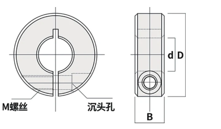
A single-split aluminum shaft clamp can be installed quickly when the shaft fit and machine access have already been checked. Most installation problems come from using the correct nominal bore in the wrong envelope, tightening on a contaminated surface or leaving the clamp screw inaccessible after the rest of the machine is assembled.
The following sequence keeps the installation focused on fit, position and serviceability rather than treating the clamp screw as the only step.
Before Installation
Confirm the EP-SCS model and the measured shaft diameter. Check the collar bore and shaft surface for burrs, chips, corrosion products or coating buildup that could prevent consistent seating.
For a replacement, compare outside diameter and width before installing the new part. A bore match does not guarantee that the new collar clears the same bearings, frames or guards as the old design.
Choose the Screw Orientation
Position the split so the clamp screw can be reached with the machine in its final assembled state. Consider guards, covers, motor bodies, carriages and nearby fasteners that may block the tool path after commissioning.
On moving systems, make sure the screw head remains outside the travel path. A serviceable orientation should not create a new collision risk.
Set the Axial Position
Move the collar to the required stop or locating point and keep it square to the shaft. If two collars are used around another component, establish the intended axial clearance or float before final tightening.
Do not use the collar to compensate for another component that is incorrectly positioned. The collar should establish the reference defined by the machine design, not mask a separate assembly problem.
Tighten the Clamp
Close the split evenly using the tightening requirement confirmed for the ordered configuration. Avoid transferring a torque value from an unrelated collar purely because the screw thread is the same.
If the application depends on a defined axial holding requirement or repeated-impact duty, that condition should be identified during selection so the installation instruction matches the actual use.
Verify the Completed Assembly
After tightening, recheck the collar position and inspect the clearance around the full mechanism. Rotate or move the machine safely through the relevant range and look for contact with carriages, bearings, covers, cables or other components.
For a stop application, verify that the contact event is intended. A setup reference that is rarely touched and a hard stop that receives repeated impact are different duties.
Repositioning and Removal
Stop and secure the machine before loosening the collar. Open the clamp enough to move it without dragging the bore across the shaft, then inspect both surfaces before resetting the position.
If the collar or shaft shows damage, contamination or corrosion, address that condition before reuse. Reinstallation should not assume that the previous position or tightening method is still appropriate after an abnormal event.
Common Installation Errors
| Error | Better Practice |
|---|---|
| Choosing from nominal equipment data | Measure the shaft at the actual collar location. |
| Ignoring OD/width | Check the full radial and axial envelope before assembly. |
| Blocking the clamp screw | Choose a serviceable orientation before surrounding parts are installed. |
| Using unrelated torque data | Use the requirement confirmed for the ordered collar/application. |
| Skipping travel verification | Check the entire moving path after installation. |
Need a Fit Review?
Send the model, measured shaft, application and a photo or drawing of the installed area. That information makes it easier to discuss screw orientation, space restrictions and replacement fit before the collar reaches the machine.